This article was originally published on August 6, 2025, and updated on March 25, 2026.
Introduction
In robotics, an encoder is a sensor that measures physical motion—such as the rotation of a motor—and converts it into electrical signals that can be processed by a robot’s control system to determine position, speed, acceleration, and direction of a mechanical system.
Types of Encoders
Encoders can be classified in several ways:
- Incremental vs. Absolute based on how position is measured
- Rotary vs. Linear for measuring rotational or linear movement
- By sensing technology — such as magnetic, optical, capacitive, and others
Absolute encoders can position within and across rotations by providing a unique position value for each shaft angle. They can still tell the exact position even after a power reset. An incremental encoder, however, does not provide absolute positional information and loses position when power is off. The main advantages of incremental encoders are its lower cost and high speed capability. The video below from US Digital, explains incremental vs absolute encoders in plain language:
Rotary encoders measure angular motion, while linear encoders measure linear motion. Rotary encoders are mounted on motor shafts and they are the most common in robotics. Linear encoders measure straight line motion and are used in CNC machines or precision stages.
Magnetic encoders use magnetic fields and Hall sensors to measure movement. They usually have lower resolution than optical encoders.
Capacitive encoders work by detecting changes in capacitance. They are resistant to dust and are typically lower cost.
Optical encoders operate using a light source and a patterned disk attached to a rotating shaft. As the disk rotates, it alternately blocks and allows light to pass through, creating a signal detected by a photosensor. This signal is then converted into electrical outputs that represent position, speed, and direction. The figure below shows the concept.

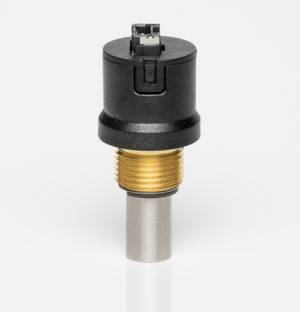
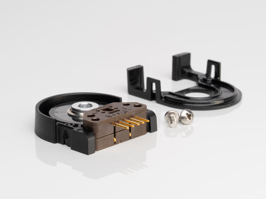
The photo below shows an example of a real optical encoder:
Applications
For high-end industrial robots, research robots, humanoids, and advanced quadrupeds, the best choice is typically absolute encoders, using either optical or high-resolution magnetic technologies. This ensures that precise joint position information is always known, which is critical for balance and smooth motion. If the robot falls or restarts, there is no need for homing. While optical encoders provide the highest accuracy and resolution, magnetic encoders are often preferred in real-world systems due to their robustness against dust, vibration, and harsh environments.
For mid-level robots and advanced DIY systems, incremental encoders may be more suitable. They are lower in cost and easy to interface with microcontrollers such as Arduino or STM32. However, as mentioned earlier, they require homing after power loss since they do not retain absolute position.
For simple or hobby-level robots, magnetic (Hall-effect) incremental encoders are often the best choice. They are very low cost, durable, and resistant to shock and dust. While they offer lower precision, they are sufficient for speed measurement and basic positioning in applications such as line followers, wheeled robots, and simple automation systems.
Encoder Placement
Encoder placement determines what motion is actually being measured. In robotic systems, especially those using gear reductions, the location of the encoder can significantly affect accuracy and control performance.
When an encoder is mounted on the motor shaft, it measures motor rotation—but not necessarily the true motion at the output joint. Mechanical elements such as gearboxes introduce backlash, elasticity, and friction, which create a difference between motor position and actual joint position.
Encoders can be mounted on the motor side or the output side. Motor-side placement is simpler, where the encoder is mounted directly on the motor shaft. However, this method does not capture gearbox-related errors, so the actual joint position may differ from the measured value.
Alternatively, the encoder can be mounted after the gearbox, at the output side, allowing measurement of the true joint position. This significantly reduces errors caused by gearbox effects, but comes at the cost of increased mechanical complexity and higher system cost. Output-side placement is preferred in applications where end-effector accuracy is critical.
In high-performance systems, both placements may be used simultaneously. The motor-side encoder is used for velocity control and torque estimation, while the output-side encoder provides accurate position feedback. This dual-encoder approach enables improved precision, stability, and advanced control strategies such as force and impedance control.
Important Concepts
Resolution:
The resolution of an encoder defines the number of measuring segments on its internal disk. In practice, this also determines how fast pulses are generated: as motor speed increases, the encoder produces pulses more frequently. This pulse rate depends on both the encoder’s pulses per revolution and the motor’s speed. If resolution is too high, the resulting pulse frequency may exceed the encoder electronics or microcontroller’s ability to process signals, leading to missed counts. Therefore, resolution should be chosen as the lowest value that still meets the required position accuracy.
Counts Per Revolution (CPR) vs. Pulses Per Revolution (PPR):
PPR refers to the number of pulses generated on a single channel per full rotation. CPR, often used interchangeably but technically different, represents the total number of countable states the controller detects; when using quadrature decoding, the controller can count multiple transitions per pulse, resulting in a higher effective count than PPR.
Quadrature Encoding (A/B channels):
Two square-wave signals offset by 90 degrees in phase. By detecting which channel leads or lags, the controller determines both position and rotation direction (clockwise or counter-clockwise).
Index Pulse (Z-channel):
A physical reference mark on the encoder disk that generates one pulse per full rotation. It serves as a precise zero point for alignment and is commonly used during homing to eliminate accumulated position error.
Edge Detection (1×, 2×, 4× Decoding):
A decoding technique that increases effective resolution by counting signal transitions (rising and/or falling edges) on A and B channels. By counting more transitions per pulse cycle, the system can achieve multiple times the base resolution of the encoder.
Gray Code Mapping:
Used primarily in absolute encoders; ensures only one bit changes between adjacent positions. This minimizes read errors that could occur if multiple bits changed simultaneously during transitions.
Shafted vs. Hollow Shaft (Shaftless):
Describes the mechanical coupling method. Shafted encoders use flexible couplings to connect to the motor and tolerate misalignment, while hollow shaft encoders mount directly on the shaft, saving space but requiring better alignment and vibration control.
Line Driver Output (Differential Signaling):
Uses complementary signal pairs (e.g., A and its inverse), typically following RS-422 standards. This allows noise rejection by cancelling interference at the receiver, making it suitable for long cable runs in industrial environments.
Homing / Referencing (Index-Based):
The initialization process required for incremental encoders. Since position is lost on power-off, the system moves to a known reference and often uses the Z-channel to establish an accurate zero position.
Open Collector vs. Push-Pull Output:
Defines how the encoder drives its output signals. Open collector outputs require an external pull-up resistor, while push-pull actively drives both high and low states, providing stronger signals for higher speeds and longer cables.
Common Encoder Problems
Dropped Counts (Cumulative Positioning Error):
This is one of the most common and frustrating issues in motion control, where the controller’s internal count no longer matches the actual motor position. It typically occurs when encoder signal frequency exceeds the processing capability of the microcontroller or the encoder interface hardware. In high-speed systems—especially when high resolution is combined with high RPM—pulses can arrive faster than the system can register them, leading to missed counts and cumulative position drift over time. Preventing this requires matching encoder resolution, motor speed, and controller capability so that signal frequency remains within the system’s maximum operating limits.
Phase Lead/Lag (Quadrature Distortion):
In a perfect setup, Channel A and Channel B are exactly 90° apart. Phase error occurs when this timing is skewed. This is usually caused by signal integrity issues such as slow rise times in long cables or improper termination, though mechanical misalignment can also contribute. When this happens, the controller struggles to determine the direction of travel, often causing the robot to jitter or vibrate when it should be holding a steady position.
Signal Noise and EMI Interference:
Standard digital inputs can mistake electrical noise for a real encoder pulse. This typically happens when high-power motor cables are run too close to low-power encoder signal wires, causing electromagnetic interference (EMI). The symptom is “ghost movement”—the encoder reports motion even when the motor is stationary. Using shielded twisted pair (STP) cabling and properly grounding the shield (typically at one end) is a common industry solution.
Index Pulse (Z-Channel) Glitching:
Because the Z-pulse occurs only once per revolution and is extremely narrow, it is the most timing-sensitive part of the signal. If a robot performs a homing routine at high speed, the controller may fail to detect the Z-pulse entirely. This results in failure to establish a correct zero position or repeated overshooting. For reliable referencing, the homing sequence should transition to a very low “seek speed” before searching for the index pulse.
Mechanical Contamination (Optical Specific):
For optical encoders, environmental conditions are a major failure factor. Dust, oil, or condensation can enter the encoder housing and block or scatter the light path. This can cause total signal loss or repeatable position errors at the same angular location. In harsh or dirty environments, such as outdoor robotics, magnetic encoders are often preferred due to their higher robustness.
Backlash vs. Encoder Truth Mismatch:
In systems with gearboxes, the encoder may not measure the true output position. When the encoder is mounted on the motor shaft, any backlash or compliance in the gearbox creates a gap between measured position and actual joint position. This becomes especially problematic during direction changes, where the motor rotates but the output does not immediately follow. The result is positioning error, oscillation, or unstable control behavior. High-performance systems address this by placing the encoder on the output side or by using dual-encoder configurations to compensate for gearbox effects.
Conclusion
With the rise of collaborative robots and humanoid systems, encoder technology continues to evolve toward higher resolution, lower latency, and more integrated sensing capabilities.
Selecting the right encoder requires balancing precision, robustness, and system constraints. Optical encoders remain the standard for high-precision applications such as clean-room robotics and CNC machines, where fine accuracy is critical, but they are sensitive to dust and contamination. Magnetic encoders, in contrast, are highly robust and resistant to harsh environments, making them well-suited for industrial and outdoor applications, though they typically offer lower resolution. Capacitive encoders provide a middle ground, combining good durability with relatively high precision, and are increasingly used in compact and space-constrained systems. In practice, the choice depends on factors such as whether absolute or incremental positioning is required, the sensing technology, mechanical integration with the motor or joint, required resolution, electrical interface compatibility, and the operating environment.
For a beginner’s summary on encoders, also visit:
Post By: A. Tuter
Article Last Updated: March 2026
Terms of Use: Unauthorized copying is prohibited; we maintain dated records to document original publication. Content is provided “as is” and may contain inaccuracies. All trademarks mentioned above, belong to their respective owners; we are not affiliated with them, and no endorsement is implied. See our Terms Page. Certain images and/or text in this post are used with permission from the right holders.