
Toolpath planning is the process of generating the precise geometric route and operating parameters that a robot or machine tool follows to perform a physical process. The tool may be a CNC cutter, welding torch, 3D-printing nozzle, spray gun, polishing tool, or inspection sensor.
Although toolpath planning and robot motion planning are closely related, they address different levels of the problem. General motion planning determines how a robot can move safely through its workspace, while toolpath planning determines how the tool should travel to accomplish a specific manufacturing or processing task. As a result, toolpath planning must consider not only geometry and collision avoidance, but also material behavior, surface quality, process speed, tool orientation, and manufacturing objectives.
The numerical examples below are illustrative order-of-magnitude estimates, not universal performance figures. Actual values depend on machine dynamics, geometry, process parameters, and manufacturing requirements.
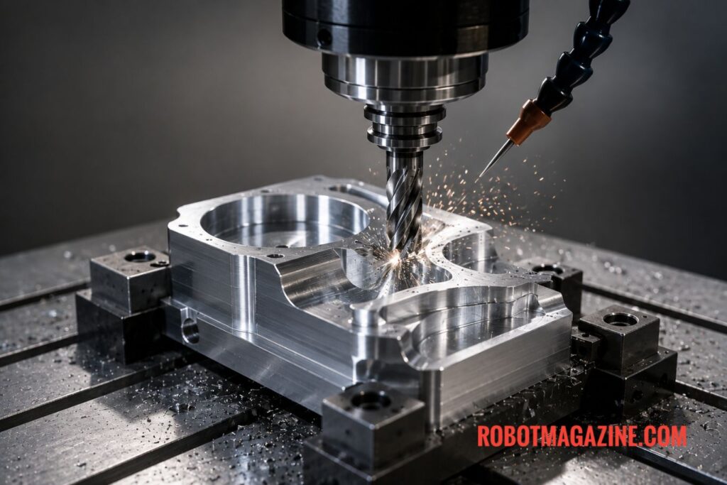
From Geometry to a Toolpath
Toolpath generation usually begins with a CAD model, point cloud, mesh, or other representation of the workpiece. The system identifies the region that must be processed and generates a sequence of tool positions and orientations.
For a simple planar surface, this might involve parallel passes across the entire region. For a complex three-dimensional surface, the toolpath may need to follow changing curvature while maintaining a particular distance and orientation relative to the surface.
The generated geometric path is then checked for reachability, collisions, joint limits, singularities, and process constraints. Finally, the path can be time-parameterized by assigning velocity and acceleration profiles before being converted into executable commands for the robot or machine controller.
Common Toolpath Patterns
The choice of path pattern affects cycle time, surface quality, tool loading, and robot dynamics.
Zig-Zag or Raster
A raster path consists of parallel passes connected by alternating turns at the boundaries. It is simple to generate and widely used in machining, additive manufacturing, painting, and surface processing.
Consider a surface requiring 20 parallel passes. A conventional raster pattern requires approximately 19 direction reversals between those passes. If each reversal takes 0.5 seconds of additional deceleration, turning, and acceleration, the transitions alone account for about 9.5 seconds of non-productive time.
This is an illustrative order-of-magnitude calculation rather than a typical industry value. The actual transition time depends strongly on machine dynamics, path geometry, acceleration limits, and process requirements.
Contour-Parallel
Contour-parallel paths follow successive offsets of the workpiece boundary. They are particularly useful when maintaining accurate boundaries and consistent coverage is important.
However, offsetting becomes more complicated around sharp corners, narrow regions, and complex geometry. The distance between neighboring contours may also need to be adjusted to maintain a consistent surface finish.
Spiral and Continuous Paths
Spiral paths provide continuous movement across a region, reducing the need for repeated stops, reversals, or tool lifts. Fermat spirals are one example of a continuous pattern that can provide smooth motion.
Other continuous or space-filling strategies, including Hilbert curves and medial-axis-based paths, can also be useful for particular additive manufacturing, polishing, and surface-processing applications.
The benefit is not necessarily that the geometric distance is always shorter. A path with smoother curvature can allow the robot or machine to maintain a higher usable feed rate because fewer abrupt accelerations and decelerations are required.
For example, if a machine can process straight sections at 500 mm/s but must slow to 200 mm/s through repeated tight turns, eliminating or smoothing those turns can substantially reduce cycle time even without reducing the total geometric distance. These speeds are illustrative; actual allowable feed rates depend on the machine, tool, material, and process.
Adaptive Toolpaths
Adaptive toolpath generation changes the path according to local geometry or process conditions. Instead of using a constant distance between every pass, the planner can vary spacing according to surface curvature, desired scallop height, deposition requirements, or cutting conditions.
For example, if a 100 mm-wide region is processed with a constant 1 mm path spacing, approximately 100 passes are required. Increasing the spacing to 1.5 mm reduces this to roughly 67 passes—a reduction of about 33%.
This does not mean that adaptive spacing will always reduce cycle time by 33%. The wider spacing is only acceptable if the resulting surface quality or material deposition remains within the required limits. The example simply illustrates the relationship between path spacing and the number of processing passes.
Toolpath Optimization
Generating a valid path is only the first step. A good toolpath should also be efficient and physically suitable for the process.
Common optimization objectives include:
Minimizing total path length
Reducing non-productive travel
Maintaining consistent surface quality
Maximizing material removal or deposition rate
Maintaining suitable tool orientation
Reducing sudden velocity and acceleration changes
Avoiding excessive cutting forces or thermal accumulation
Minimizing tool lifts and retractions
Different algorithmic approaches address these objectives. Iso-scallop strategies attempt to maintain relatively consistent scallop height between neighboring machining passes. Curvature-adaptive methods modify path spacing according to local surface geometry.
When many independent path segments must be connected, graph-based optimization can determine an efficient visiting order, similar in principle to the Traveling Salesman Problem (TSP). For example, if 100 processing segments each require an average of 20 mm of unnecessary travel because they are connected inefficiently, optimizing their sequence could potentially eliminate around 2 meters of non-processing movement.
Feed-rate optimization provides another important layer. Time-optimal feed-rate scheduling adjusts velocity according to curvature, acceleration limits, cutting forces, or other process constraints rather than simply commanding a constant speed.
Collision, Reachability, and Robot Configuration
For robotic applications, geometric toolpath quality alone is not sufficient. The robot must actually be capable of following the path.
Collision checking must consider the complete system, including the tool, tool holder, robot links, workpiece, fixtures, and surrounding equipment. This is especially important for 5-axis CNC machines and 6-DoF industrial robots, where tool orientation can create collisions even when the tool tip itself is positioned correctly.
Tool orientation planning is therefore often coupled with singularity avoidance and configuration selection. A robot may have several joint configurations capable of reaching the same tool position, and the planner can select configurations that provide better clearance, avoid joint limits, or reduce the risk of approaching a singularity.
For redundant robots with more degrees of freedom than required by the task, redundancy resolution provides additional freedom to optimize the robot configuration while following the desired toolpath.
Toolpath Planning in Manufacturing
The objectives and constraints vary considerably between applications.
Subtractive Manufacturing
In CNC milling, turning, and robotic machining, the objective is generally to remove material efficiently while maintaining dimensional accuracy and surface quality. Cutting forces, tool deflection, heat generation, tool wear, and gouging must be considered.
For example, maximizing material removal rate alone is not necessarily optimal. Increasing feed rate may shorten machining time, but excessive cutting forces can increase tool deflection and produce dimensional errors or poor surface finish.
Additive Manufacturing
In 3D printing and Directed Energy Deposition (DED), the toolpath controls where material is deposited. The planner must consider deposition rate, layer adhesion, thermal effects, overhangs, bead geometry, and synchronization between tool movement and material flow.
A deposition system moving at 100 mm/s, for example, must coordinate material flow with that movement. Increasing the travel speed without adjusting deposition can produce insufficient material, while excessive deposition can create overfilled regions. The value is illustrative rather than a prescribed operating speed.
Welding and Spraying
Robotic welding requires the torch to follow a seam while maintaining appropriate orientation, distance, and travel speed. Spray painting and coating applications similarly require controlled surface coverage and tool orientation, often across complex three-dimensional surfaces.
Polishing and Surface Processing
Polishing and finishing applications may require overlapping passes with carefully controlled pressure, orientation, and speed. Here, toolpath design directly affects the uniformity of material removal and the resulting surface quality.
Connecting Multiple Path Segments
Many manufacturing tasks generate numerous separate path segments rather than one continuous curve. Simply processing them in the order in which they were generated can produce substantial unnecessary travel.
Graph-based approaches can treat individual segments as nodes or edges and determine an efficient connection sequence. The objective may be to minimize travel distance, tool lifts, retractions, or changes in orientation.
The quantitative impact can become significant in large jobs. If optimizing the sequence removes 2 m of unnecessary travel and the robot’s average transit speed is 500 mm/s, that represents approximately 4 seconds saved per cycle. Across 1,000 production cycles, this becomes roughly 67 minutes of accumulated cycle-time savings.
Again, this is an illustrative calculation: actual savings depend on the robot’s transit speed, acceleration and deceleration, path geometry, and the number of segments.
Modern Toolpath Planning
Toolpath planning is increasingly moving beyond purely geometric algorithms.
Optimization-based methods can simultaneously consider geometry, robot configuration, process parameters, and dynamic constraints. Machine-learning methods are also being investigated for predicting process quality, selecting path parameters, and adapting toolpaths based on manufacturing data.
Another important development is real-time adaptive planning. Sensors can provide information about forces, temperature, deposited material, surface condition, or tool wear while the process is running. The system can then modify the toolpath or process parameters in response to actual conditions rather than relying entirely on an offline plan.
Digital twins provide another layer of integration by allowing the planned toolpath and robot behavior to be simulated before execution. This can help identify collisions, unreachable regions, poor orientations, and inefficient trajectories before the physical process begins.
Multi-robot and multi-tool manufacturing creates additional planning challenges. When several robots or tools operate on the same workpiece, the planner must coordinate their paths to prevent collisions while minimizing idle time and balancing the workload.
Software and Tooling Ecosystem
Toolpath planning is implemented through a broad software ecosystem. Industrial CAM systems generate toolpaths for CNC and manufacturing processes, while proprietary robot programming and offline-programming environments convert process paths into robot-specific programs.
In robotics research and advanced industrial applications, frameworks such as ROS-Industrial can connect motion planning, perception, simulation, and robot control components. Open-source motion-planning libraries and simulation environments can also be used to develop and test customized planning algorithms.
In practice, sophisticated systems often combine several layers: CAD/CAM software generates the process path, a robot motion planner determines feasible robot configurations, simulation software validates the result, and the robot controller executes the final trajectory.
Toolpath Planning vs. Robot Motion Planning
The distinction can be summarized simply:
Toolpath planning determines where and how the tool should travel to perform the process.
Robot motion planning determines how the robot’s joints should move to execute that toolpath safely and within its physical constraints.
For example, in robotic welding, toolpath planning determines the welding seam, torch orientation, and process movement along the seam. Robot motion planning then determines the joint configurations and movements required to follow that path while avoiding collisions, joint limits, and singularities.
Together, these processes transform a manufacturing task into an executable robot trajectory. Effective toolpath planning therefore influences geometric accuracy, cycle time, surface quality, process reliability, mechanical loading, and overall manufacturing efficiency.
Terms of Use: Unauthorized copying is prohibited; we maintain dated records to document original publication. Content may contain inaccuracies. See our Terms Page.